
Hey,
Today's blog we are going to use ADXL345
Accelerometer with raspberry pi.
WHAT YOU NEED :
Raspberry pi 3
SD card (8gb+ recommend)
Power supply
ADXL345 accelerometer
Breadboard
CIRCUIT :
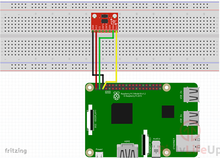
1. Before we can get our Raspberry Pi to retrieve data from our ADXL345 Accelerometer, there are a few changes we must make to the Pi’s configuration.
Let’s first ensure that everything is up to date by running the following two commands.
sudo apt-get update
sudo apt-get upgrade
2. Once the Raspberry Pi has finished updating, we will need to go ahead and launch the Raspberry configuration tool so that we can enable I2C on the Raspberry Pi.
Run the following command to launch the raspi configuration tool.
sudo raspi-config3. On this screen, you need to head to the “5 Interfacing Options” menu.
You can navigate the raspi-config tools menus by using the arrow keys. Use the ENTER key to select particular options.
4. Now within the interfacing options menu go ahead and select “P5 I2C“.
When asked if you would like to enable the ARM I2C interface, select “<YES>“.
5. After enabling the I2C interface, you will need to restart your Raspberry Pi by running the following command.
sudo reboot6. Now that we have enabled I2C and restarted the Raspberry Pi, we can now proceed to install the packages that we will rely on to talk with our accelerometer.
Run the following command to install.
sudo apt-get install python3-dev python3-pip python3-smbus i2c-tools -y6. With all our required packages installed let’s now check to see whether our Raspberry Pi can see our ADXL345 Accelerometer.
We can do that by running the following command.
sudo i2cdetect -y 1From this command, you should see a fair bit displayed on the command line. Within this result, you should at least see a number such as “53“.
If nothing appears then make sure you have connected your ADXL345 Accelerometer to the Raspberry Pi correctly and that all solder points on the pins of the sensor are clean. If you see an error try re-enabling I2C again
CODING THE SCRIPT :
1. With all the packages that we need now installed to the Raspberry Pi, we can now proceed to write a small Python script. This script is so that we can read information from the accelerometer.
To talk with the ADXL345, we will be making use of Adafruit’s ADXL34x Python library. To install this library so that we can utilize it, you need to run the following pip command.
sudo pip3 install adafruit-circuitpython-ADXL34x2. With the library installed, we can now proceed to code our small Python script.
Begin writing this file by running the following command.
nano ~/accelerometer.py3. Within our new script, write the following lines of code.
import timeWe start by importing the “time” library. We utilize the “time” library so that we can put the script to sleep for a short period.
import boardHere we import Adafruit’s “board” library. This unique library is designed to quickly know what pins are available on a device.
So instead of specifying a specific pin, we can use something like “board.scl” and that will return the correct pin for the current microcontroller. In our case, this is the Raspberry Pi.
import busioNext, we import Adafruit’s “busio” module. This module contains a variety of different libraries to handle various serial protocols. We will be using this modules library for handling the I2C serial protocol.
import adafruit_adxl34xNow we import the “adafruit_adxl34x” library. This library contains all the code we need for reading information from our ADXL345 accelerometer and makes the process incredibly simple.
i2c = busio.I2C(board.SCL, board.SDA)Here we utilize the “busio” library to prepare an I2C connection for our current boards SCL and SDA pins. We store the handle into our “i2c” variable.
accelerometer = adafruit_adxl34x.ADXL345(i2c)We now instantiate the ADXL345 library into our “accelerometer” object. We will utilize this object to read and obtain information from our sensor. Into the constructor for the library, we pass in our I2C handle.
while True:
    print("%f %f %f"%accelerometer.acceleration)
    time.sleep(0.5)
Here we start an infinite loop by using “while True:“.
Within this infinite loop, we print out the X, Y, and Z acceleration values that have been retrieved from the accelerometer by the library.
Once we have printed the X, Y, and Z values, we then put the script to sleep for half a second.
We sleep the script to stop it from flooding the command line with the values provided by the accelerometer.
4. The final version of the accelerometer code should end up looking like what we have below. Check your final code against this.
import time
import board
import busio
import adafruit_adxl34x

i2c = busio.I2C(board.SCL, board.SDA)
accelerometer = adafruit_adxl34x.ADXL345(i2c)

while True:
    print("%f %f %f"%accelerometer.acceleration)
    time.sleep(1)
When you are happy that all the code is correct you can save it by pressing CTRL + Xthen Y followed by ENTER.
5. With the code now done, let’s go ahead and run the script by running the following command.
python3 ~/accelerometer.py6. By running this code, you should start seeing the values being read in from the accelerometer.
0.117680 0.313813 8.355266
0.117680 0.313813 8.394492
0.117680 0.313813 8.355266
0.117680 0.353039 8.316039
0.117680 0.431493 8.316039
0.117680 0.313813 8.276813
7. Now that we know that the accelerometer is returning data and that the Raspberry Pi is reading correctly, we can explore some of the other functionality of the ADXL345 library.
ACCELEROMETER LIBRARIES:
1. In this section of this Raspberry Pi accelerometer tutorial, we will be exploring some of the other functionality provided by Adafruit’s ADXL345 accelerometer library.
In particular, we will be looking at the “events” that the library can automatically detect when enabled.
To begin, let’s open our “accelerometer.py” script by using the following command.
nano ~/accelerometer.py2. Within the file, find and add the lines shown below. We will explain what each new section is for and what it does.
Find
accelerometer = adafruit_adxl34x.ADXL345(i2c)Add the following lines below the line above.
accelerometer.enable_freefall_detection(threshold=10, time=25)This line enables the libraries freefall detection event. It takes in two variables, one being the threshold, the other is the time.
The threshold is the value that acceleration on all axes must be under for it to register as a drop. The scale factor is 62.5 mg, so our example is 10*62.5=625 mg.
Next, the time variable is the amount of time that acceleration on all axes must be less than the threshold for them to register as being dropped. The scale factor is 5 ms, so our example is 25×5=125ms.
accelerometer.enable_motion_detection(threshold=18)This line enables the libraries motion detection event. It takes in one variable, the threshold.
The threshold variable is the value that acceleration on all axes must exceed for a motion to be detected. If you find this is too sensitive or not sensitive enough you can modify this value. The scale factor is 62.5 mg, so our example is 18*62.5=1125 mg.
accelerometer.enable_tap_detection(tap_count=1, threshold=20, duration=50, latency=20, window=255)This line enables the libraries tap detection event.
The tap_count variable is whether you want to detect a single tap or a double tap. Set this to 1 for single tap or 2 for double taps.
Next is the threshold variable, and this is for how sensitive you want the tap to be, the higher the value, the less sensitive the code will be to detecting a tap. Like the other threshold variables the scale factor is 62.5 mg.
The duration variable is the length of time in nanoseconds that the motion should occur. If the duration of the movement is too long, it will not be detected as a tap. This value needs to be in ms.
Now the latency variable is the length of time after the initial impulse to start looking for the second tap. The latency value should be in ms.
Lastly, the window variable is the length of time in which the code should look for the second tap to occur. Again, this value should be in ms.
Find
print("%f %f %f"%accelerometer.acceleration)Add the following lines below
    print("Dropped: %s"%accelerometer.events["freefall"])
    print("Tapped: %s"%accelerometer.events['tap'])
    print("Motion detected: %s"%accelerometer.events['motion'])
These additional lines print out the status of all the events that we activated earlier in the script. These print lines will let you know whether any of the events are currently being triggered.
Typically you won’t be checking for all these events at one time.
3. With all the changes made to the accelerometer code, it should look a bit like what we have below.
import time
import board
import busio
import adafruit_adxl34x

i2c = busio.I2C(board.SCL, board.SDA)
accelerometer = adafruit_adxl34x.ADXL345(i2c)
accelerometer.enable_freefall_detection(threshold=10, time=25)
accelerometer.enable_motion_detection(threshold=18)
accelerometer.enable_tap_detection(tap_count=1, threshold=20, duration=50, latency=20, window=255)

while True:
    print("%f %f %f"%accelerometer.acceleration)
    print("Dropped: %s"%accelerometer.events["freefall"])
    print("Tapped: %s"%accelerometer.events['tap'])
    print("Motion detected: %s"%accelerometer.events['motion'])
    time.sleep(0.5)
When you are happy all the code is correct you can save it by pressing CTRL + X then Yfollowed by ENTER.
4. With the code now done, let’s go ahead and run the script by running the following command.
python3 ~/accelerometer.py5. By running this code, you should start seeing text be printed to the command line, showing the X, Y, and Z positions received as well as the status of all the events.
0.235360 0.353039 8.355266
Dropped: False
Tapped: False
Motion detected: False
With that all done, you should now have some understanding of how to use your ADXL345 accelerometer with the Raspberry Pi.
Making electronics project is too pretty simple with Us.
Join and Make with Us.
Comments