
Hey,
In today's blog we are going to make a IOT based Garage door lock.
WHAT YOU NEED:
Raspberry pi
Relay module
Connecting wire
CIRCUIT DIAGRAM:

Here, we have created a web server using Flask, which provides a way to send the commands from webpage to Raspberry Pi to control the Robot over the network. Flask allows us to run our python scripts through a webpage and we can send & receive data from Raspberry Pi to web browser and vice versa. Flask is a microframework for Python. This tool is Unicode based having built-in development server and debugger, integrated unit testing support, support for secure cookies and its easy to use, these things make it useful for the hobbyist.
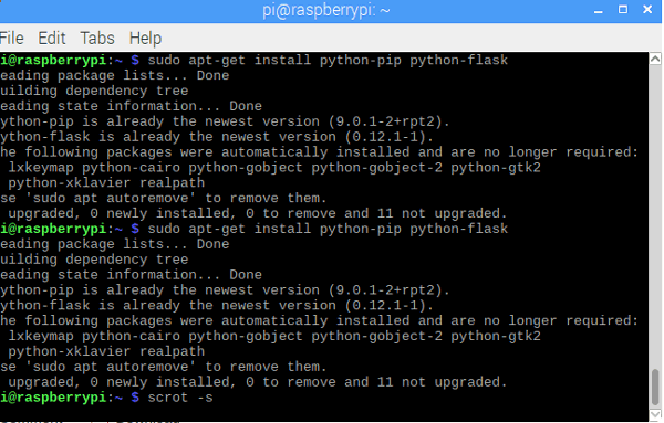
Run the following commands to install the flask in your Raspberry Pi:
sudo apt-get update
sudo apt-get install python-pip python-flask
Now, run the pip command to install Flask and its dependencies:
sudo pip install flask
You can learn more about the programming using Flask here, also check our previous projects where we have used Flask to control robot through webserver, send the message from Webpage to Raspberry Pi and send weight value to Raspberry Pi in Smart Container.
Now, we will write a python script for our garage door web server.
CREATING PYTHON SCRIPT:
This script will interact with our Raspberry Pi GPIOs and sets up the web server. So, this is the core script for our application. Complete Python Script for door opener is given at the end, here we have explained few parts of it.
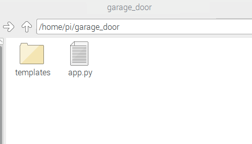
First, make a folder. All other required folders should be in this folder only. Run below commands to make folder and the create python file named app.py inside this folder.
mkdir garage_door
cd garage_door
nano app.py
This will open the Nano editor where we have to write the script.
Start by including important libraries.
import RPi.GPIO as GPIO
from flask import Flask, render_template, request
app = Flask(__name__, static_url_path='/static')
Now, create a dictionary as pins to store the pin number, name, and pin state. You can use more than one pin according to your need.
pins = {
   14 : {'name' : 'Garage Door', 'state' : GPIO.LOW}
   }
Then, set the pin as output and make it low initially.
for pin in pins: GPIO.setup(pin, GPIO.OUT) GPIO.output(pin, GPIO.LOW)
Now, make a main function to read pin state and store this state in a variable.
@app.route("/")
def main():
   for pin in pins:
      pins[pin]['state'] = GPIO.input(pin)
..
We have to pass this data to our html page so, that we can control the input button state.
return render_template('main.html', **templateData)
Now, make a function to handle the requests from the URL with the pin number and action in it.
@app.route("/<changePin>/<action>", methods=['GET', 'POST'])
def action(changePin, action):
Convert the pin from the URL into an integer.
changePin = int(changePin)
If the action part of the URL is "open," then do the following.
   if action == "open":
      GPIO.output(changePin, GPIO.HIGH)
   if action == "close":
      GPIO.output(changePin, GPIO.LOW)
You can copy the complete script from the end of this tutorial and save it using ctrl+x and then press enter. We have done with the python script. Now, we have to make a HTML page to interact with the python script.
CREATING HTML PAGE :
In the same garage_door folder, create another folder named templates and inside this folder make an .html file using below commands.
mkdir templates
cd templates
nano main.html
In the nano text editor, write the html code. You can edit the <head> part of the page and style it according to your choice. I have just used the third party css scheme using link tag. The complete HTML code is given below:
<!DOCTYPE html>
<head>
   <title>Garage Door Web server</title>
  <link rel="stylesheet" href="https://www.w3schools.com/w3css/4/w3.css">
   <script src="https://maxcdn.bootstrapcdn.com/bootstrap/3.3.6/js/bootstrap.min.js"></script>
</head>
<center>
<body>
   <h1>Garage Door Web server</h1>
   {% for pin in pins %}
   <h2>{{ pins[pin].name }}
   {% if pins[pin].state == true %}
      is currently <strong>Open</strong></h2><div class="row"><div class="col-md-2">
      <a href="/{{pin}}/close" class="w3-button w3-blue" role="button">Close</a></div></div>
   {% else %}
      is currently <strong>Close</strong></h2><div class="row"><div class="col-md-2">
      <a href="/{{pin}}/open" class="w3-button w3-black" role="button">Open</a></div></div>
   {% endif %}
   {% endfor %}
</body>
</center>
</html>
Here the important part is to create a button to open and close the door and assign a state to open and close button. The button will send and fetch the GPIO state from the python script.
You can use the above given HTML code in the editor and save it. Now the web server is ready to launch.
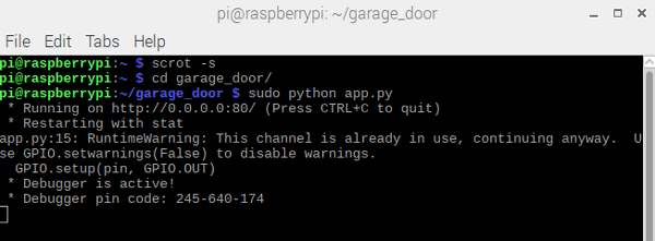
Open the terminal and navigate to garage_door folder and run the below command
sudo python app.py
Open the browser and enter your raspberry pi IP address and hit enter. To find your IP address you can run the below command in terminal.
hostname -I
You will see a page like this.
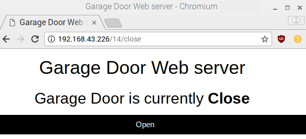
Make sure the relay module is connected to raspberry pi. Press Open button to switch on the Relay or to open the Garage Door. You can also see the state of the relay. As soon as you turned On the Relay, button text will be changed Close to turn off the relay. Now when you click the button again the relay will be turned off and the button text will be changed to Open again.
To stop the server press ctrl+c .
So just connect this relay to some Door Opener mechanism, which are readily available in market, and start controlling the garage door using Smartphone.
CODE :
import RPi.GPIO as GPIO
from flask import Flask, render_template, request
app = Flask(__name__, static_url_path='/static')
GPIO.setmode(GPIO.BCM)
pins = {
14 : {'name' : 'Garage Door', 'state' : GPIO.LOW}
}
for pin in pins:
GPIO.setup(pin, GPIO.OUT)
GPIO.output(pin, GPIO.LOW)
@app.route("/")
def main():
for pin in pins:
pins[pin]['state'] = GPIO.input(pin)
templateData = {
'pins' : pins
}
return render_template('main.html', **templateData)
@app.route("/<changePin>/<action>", methods=['GET', 'POST'])
def action(changePin, action):
changePin = int(changePin)
deviceName = pins[changePin]['name']
if action == "open":
GPIO.output(changePin, GPIO.HIGH)
if action == "close":
GPIO.output(changePin, GPIO.LOW)
for pin in pins:
pins[pin]['state'] = GPIO.input(pin)
templateData = {
'pins' : pins
}
return render_template('main.html', **templateData)
if __name__ == "__main__":
app.run(host='0.0.0.0', port=80, debug=True)
GPIO.cleanup()
Making electronics project is too pretty simple with Us.
Join and Make with Us.
Comments